
Driving a NEMA Stepper Motor with TB6600 – Rotary Encoder – Arduino
Stepper motors are widely used in various applications that require precise and controlled movements. To effectively drive a stepper motor, a reliable and efficient stepper motor driver is essential. One such driver is the TB6600, known for its versatility and compatibility with NEMA 23 motors.
In this article, we will move a stepper motor back and forth according to the value set on the Oled screen with the help of a rotary encoder.
Before you start, it may be useful to take a look at these articles: Stepper Motors, KY-040 Rotary Encoder, TB660 Motor Driver.

The materials we will use in this application are:
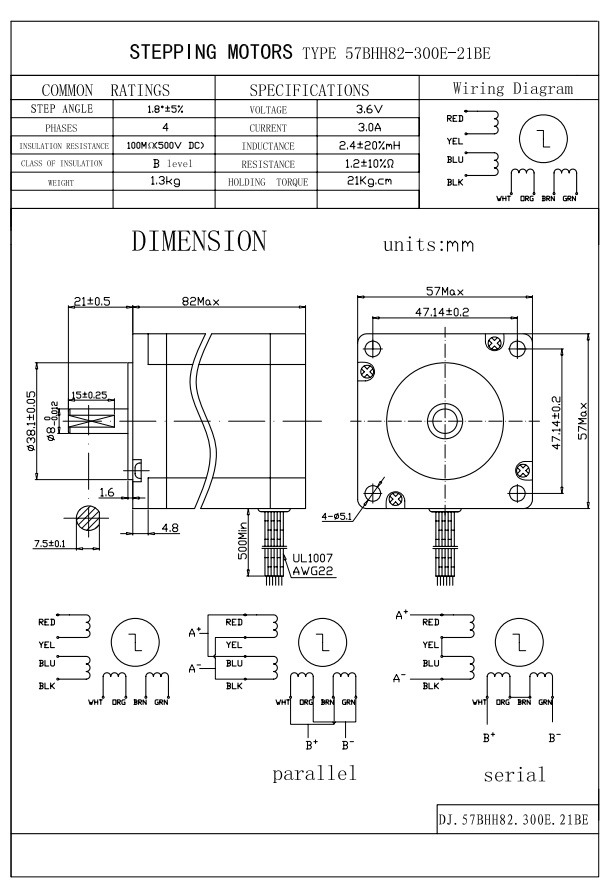
- Nema 23 stepper motor (Model No: 57BHH82-300E-21BE)
- TB6600 Motor driver
- Arduino Uno
- KY-040 Rotary Encoder
- Oled Screen
- Jumper Cables
- Breadboard
- Mean Well LRS-50-12 Power Supply
Making Connections
According to the information in the PDF of the Stepper Motor below, we will make the parallel connection on the TB6600 motor driver.
High Voltage Side of the TB6600
Vcc – 12V Output of the Power Supply
GND – GND Output of the Power Supply
(A+) – Red and Blue Wires of Stepper Motor
(A-) – Yellow and Black wires of Stepper Motor
(B+) – White and Brown wires of Stepper Motor
(B-) – Orange and Green wires of Stepper Motor
*Please check the cables and colors of the stepper motor you have. Some motors may have 4 wires and some motors may have 8 wires.
Signal Side of the TB6600
PUL(-) and DIR(-) to Arduino’s GND
PUL(+) to Arduino’s D5 pin
DIR(+) to Arduino’s D2 pin
ENA(+) to Arduino’s D8 pin
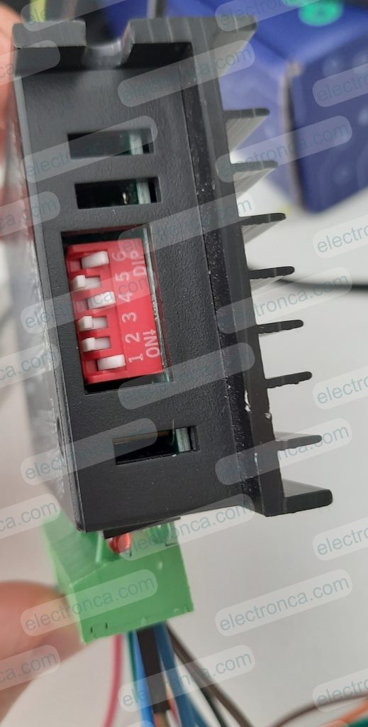
Set Dip Switch of TB6600 for Current and Microstep needs
Wiring Rotary Encoder
Encoder A to Arduino’s D6 pin
Encoder B to Arduino’s D7 pin
Encoder Button (sw) to Arduino’s D12 pin.
*For sw of Encoder: connection from 5V to D12. connection from D12 via 10k to GND
Wiring OLED Display
Vcc to Arduino’s 5V
Gnd to Arduino’s GND
SCL to Arduino’s A4
SDA to Arduino’s A5

CODE For the Application
Upload this Code to your Arduino Board via Arduino IDE after connections made carefully.
const int stepPin = 5;
const int dirPin = 2;
const int enPin = 8;

#define encoderA 6
#define encoderB 7
#define encoderButon 12 // connection from 5V to D12. connection from D12 via 10k to GND

int counter = 0;
int aState;
int aLastState;

void stepMotor();
void Gui();
#include <Wire.h>
#include <Adafruit_GFX.h>
#include <Adafruit_SH1106.h>

#define OLED_RESET 4
Adafruit_SH1106 display(OLED_RESET);

#define LOGO16_GLCD_HEIGHT 16
#define LOGO16_GLCD_WIDTH  16

#if (SH1106_LCDHEIGHT != 64)
#error("Height incorrect, please fix Adafruit_SH1106.h!");
#endif

void setup()
{
    Serial.begin (9600);
    display.begin(SH1106_SWITCHCAPVCC, 0x3C);  // initialize with the I2C addr 0x3D (for the 128x64)
    display.clearDisplay();

    pinMode(stepPin,OUTPUT);
    pinMode(dirPin,OUTPUT);
    pinMode(enPin,OUTPUT);
    digitalWrite(enPin,LOW);

    pinMode (encoderA,INPUT);
    pinMode (encoderB,INPUT);
    pinMode (encoderButon,INPUT);

    aLastState = digitalRead(encoderA);   // Reads the initial state of the encoderA
}

void loop()
{
    int buton_state = digitalRead(encoderButon);

    if(buton_state == 0)
    {
      aState = digitalRead(encoderA); // Reads the "current" state of the encoderA
      // If the previous and the current state of the encoderA are different, that means a Pulse has occured
      if (aState != aLastState)
      {
        // If the outputB state is different to the outputA state, that means the encoder is rotating clockwise
        if (digitalRead(encoderB) != aState)
        {
          counter =counter +5;
        }
        else
        {
          counter =counter -5;
        }
        Serial.print("Position: ");
        Serial.println(counter);
      }
      aLastState = aState; // Updates the previous state of the outputA with the current state

      if(digitalRead(buton_state)!=0)
      {
        Gui();
        buton_state=0;
      }
    }

    else if(buton_state == 1)
    {
      stepMotor();
    }


}

void stepMotor()
{
  if(counter >= 0)
  {
    digitalWrite(dirPin,HIGH); // Enables the motor to move in a particular direction
    for(int x = 0; x < counter; x++)
    {
      digitalWrite(stepPin,HIGH);
      delayMicroseconds(1000);
      digitalWrite(stepPin,LOW);
    }
    delay(200);
  }

  if(counter < 0)
  {
    int counterP = counter*(-1); //turns into negative value to positive

    digitalWrite(dirPin,LOW); //Changes the direction of rotation
    for(int x = 0; x < counterP; x++)
    {
      digitalWrite(stepPin,HIGH);
      delayMicroseconds(1000);
      digitalWrite(stepPin,LOW);
    }
    delay(200);
  }
}

void Gui()
{
    display.clearDisplay();
    display.setTextSize(2);
    display.setTextColor(WHITE);

    display.setCursor(55,25);
    display.println(counter);

    display.display();

}
Output of the Application
Here, you can watch the forward and reverse rotation of a stepper motor using the TB6600 driver and Rotary Encoder, according to the values set on the OLED screen.
Hello;
Do you have the step file of the 57BHH82-300E-21BE engine model?
this web site (link) may be helpful.