
What Is Stepper Motor? Stepper Motor Principles
What is stepper motor? How to drive a stepper motor? What is step angle? Stepper motor principles.
Stepper motors are special motors used where precise control of movement and position is required.
As the name suggests, stepper motors rotate in certain steps. These steps are controlled by applying pulse voltage to a suitable winding of the motor. Depending on the design (construction) of the motor, the stepper motor can rotate in angle ranges of 90°, 45°, 18° or less.
By changing the pulse rate, the one-step movement of the motor can be slowed down a lot, or it can be increased to 4000rpm.
Stepper motors can rotate clockwise or counterclockwise. This process depends on the sequence of pulse voltages applied to the phase windings.
A stepper motor is a special type of synchronous motor that is designed to rotate a certain degree for each electrical pulse received from its controller. Typical steps are 7.5° or 15° degrees per pulse.
Where Are Stepper Motors Used?
These motors are used in many control systems because the position of the shaft or other part of the machine can be precisely controlled with these motors.
The behavior of stepper motors depends on the power source that drives the motor. The pulses obtained from the power supply are controlled by the microprocessor or computer.
Pulses are counted and stored by the computer processor. Clockwise pulses are treated as (+), while counterclockwise pulses are treated as (-). As a result, step counts are always known. Since the step intervals are known exactly, the number of revolutions is also known precisely. Due to this feature, the stepper motor is used in devices that require very precise position control; printer, tape recorder, valve, plotter etc. preferable.
Rotor Structure of Stepper Motors
Stepper motors have two different rotor structures: permanent magnet type and reluctance type.
The permanent magnet type has a permanent magnet rotor. The reluctance type stepper motor has a ferromagnetic rotor without permanent magnetism.
In general, the permanent magnet step motor produces more torque than the reluctance type. The permanent magnet step motor has a torque consisting of both the permanent magnetic field in the rotor and the reluctance effects.
Stepper Motor and Control Unit

A Stepper Motor’s Diagram
You can find a simple stepper motor structure and its associated controller in the figure.
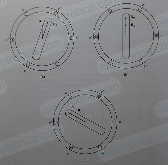
Examine the figure below to understand the operation of the stepper motor. This figure shows a two-pole three-phase stator with a permanent magnet rotor. If a DC voltage is applied to phase a of the stator but not to phases b and c, then a torque aligned with the stator magnetic field Bs will be induced in the stator as in case (b).
A Step Motor Rotor- Stator
(a) A voltage V is applied to phase a of the stator, causing a current to flow in phase a and producing the stator magnetic field Bs. The interaction of Br and Bs produces a counterclockwise torque in the rotor.
(b) When the rotor coincides with the stator magnetic field, the net torque drops to zero.
(c) A -V voltage is applied to phase c such that a current flows in this phase and produces the stator magnetic field Bs. Br and Bs interactions produce a counterclockwise torque in the rotor. This causes the rotor to coincide with the new position of the magnetic field.
Assume that phase a is switched and a negative DC voltage is applied to phase c. The new stator magnetic field rotates 60° degrees relative to the previous magnetic field, and the rotor of the motor follows it. The table below shows the rotor position in increments of 60° degrees as a function of the voltage applied to the stator.
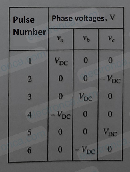
60° increments per step according to applied voltages by phase
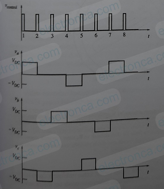
A sketch of the controller’s output voltage as a series of control pulses is given to the input.
For example, if the stepper motor has 8 poles, the mechanical angle of the motor shaft will change by 15° degrees per step.
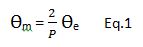
Eq.1 gives the mechanical angle of a stepper motor as a function of the electrical angle.
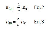
If we take the derivative of both sides of this equation with respect to time, we obtain the relationship between the electrical and mechanical rotation speeds of the motor.
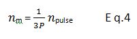
Since there are six input pulses per revolution, the relationship between revolutions per minute and pulses per minute and the speed of the motor is:
An Example Stepper Motor Question
The three-phase permanent magnet stepper motor required for an application must be able to control the position of the shaft in 7.5° degree steps and accelerate up to 300rpm.
a) How many poles should this motor have?
b) What will be the control pulse rate received by the control circuit of the engine when driven at 300 rpm?
Solution
a. In a three-phase stepper motor, each pulse advances the position of the rotor by 60 electrical degrees. This advancement should correspond to 7.5° mechanical degrees. If we use equation 1 for P;
P = 2 e/
m = 2(60/7,5) = 16 poles
b. If we use equation 4 for n pulses;
n pulse = NPnm
= 3 x16 x300 = 240 pulse/s