Direct Memory Access (DMA) – RealTerm Example – CubeMX
Starting with STM32, Nucleo Board, How to Use DMA? Direct Memory Access of STM Microcontrollers
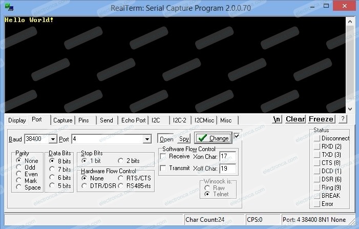
In this article, we are making an application with the DMA peripheral on our Nucleo board. We examine the application output through the RealTerm program.
Before starting the article, it will be useful for you to review our UART/USART communication article in terms of configuration and program usage.
Introduction to DMA
The direct memory access (DMA) controller is a bus master and system peripheral.
The DMA is used to perform programmable data transfers between memory-mapped peripherals and/or memories, upon the control of an off-loaded CPU.
The DMA controller features a single AHB master architecture.
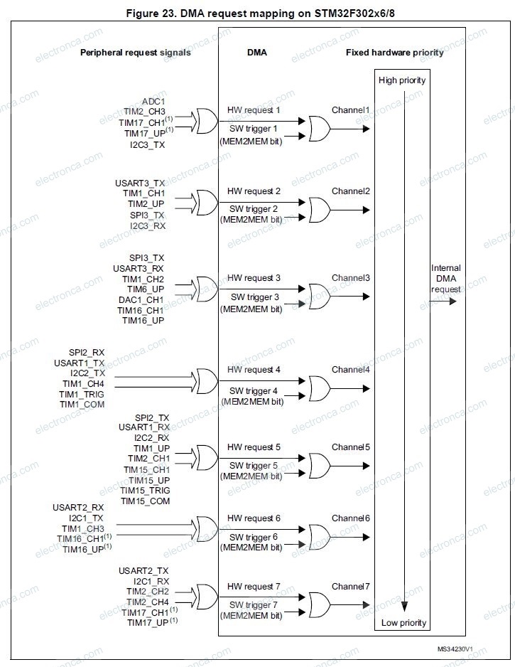
There is one instance of DMA with up to 7 channels, except for the STM32F302xB/C/D/E devices that also include a DMA2 with 5 channels.
Each channel is dedicated to managing memory access requests from one or more peripherals. Each DMA includes an arbiter for handling the priority between DMA requests.
*Please refer our short DMA article for extra notes.
DMA with Cortex-M
Typically, the Cortex-M core processor uses instructions to transport data. Typically, this data is transferred to and from peripherals and internal memory. Important CPU cycles that may be used in an embedded system with limitations are wasted on this data transmission operation.
The DMA controller was created for this purpose. In many situations, it can take over the data transport function, freeing up the main CPU to handle other crucial embedded system tasks.
Although the DMA controller is more closely related to a co-processor than a peripheral, it is technically a peripheral device.
In contrast to other peripherals, the DMA controller has the ability to function as a bus master.
DMA Controller Details
Two master ports are present in every STM32 DMA controller; the memory port is the one that links to internal memory, including flash and SRAM.
The Advanced High-Performance Bus (AHB) is connected to the other port, which is called the peripheral port. The slave peripherals are connected to the AHB in turn. The peripheral connector of the STM32F302R8 DMA controller can also be connected to a memory control circuit, enabling memory-to-memory transfers.
Additionally, STM32 DMA controllers include one slave port that is linked to the AHB bus. This makes it possible to program the DMA controller from the core CPU, which is the other master.
Each of the seven configurable, independent channels on the STM32F302R8 DMA controller is attached to a different hardware line.
These are how the slave peripherals can request a response from the DMA controller.
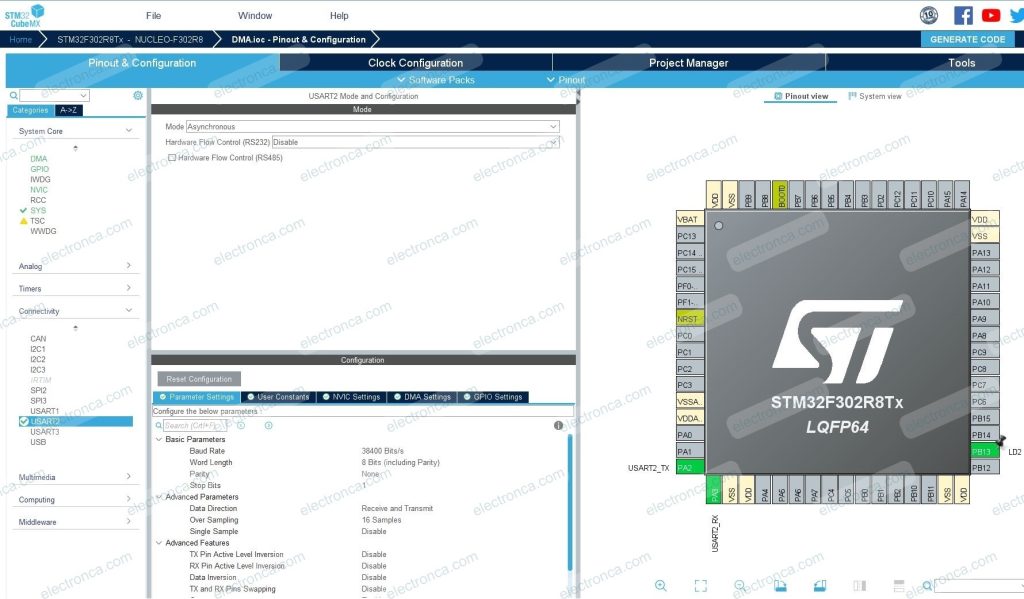
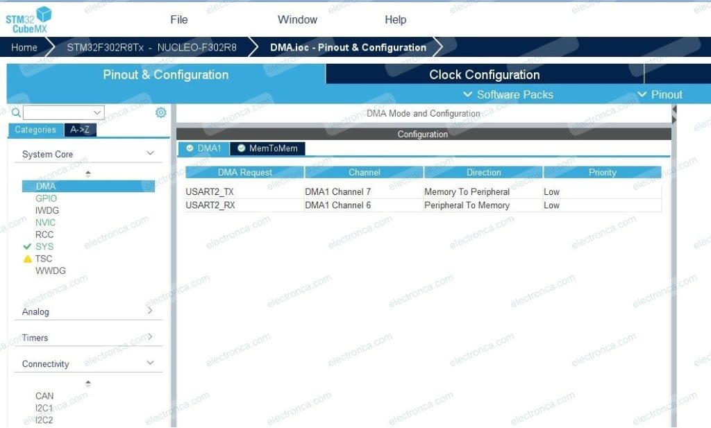
CubeMX Configurations for Nucleo Board and Code Generation
KEIL CODE
/* USER CODE BEGIN Header */
/**
******************************************************************************
* @file : main.c
* @brief : Main program body
******************************************************************************
* @attention
*
* <h2><center>© Copyright (c) 2023 STMicroelectronics.
* All rights reserved.</center></h2>
*
* This software component is licensed by ST under BSD 3-Clause license,
* the "License"; You may not use this file except in compliance with the
* License. You may obtain a copy of the License at:
* opensource.org/licenses/BSD-3-Clause
*
******************************************************************************
*/
/* USER CODE END Header */
/* Includes ------------------------------------------------------------------*/
#include "main.h"
#include "stm32f3xx_hal.h"
#include <string.h>
/* Private includes ----------------------------------------------------------*/
/* USER CODE BEGIN Includes */
/* USER CODE END Includes */
/* Private typedef -----------------------------------------------------------*/
/* USER CODE BEGIN PTD */
/* USER CODE END PTD */
/* Private define ------------------------------------------------------------*/
/* USER CODE BEGIN PD */
/* USER CODE END PD */
/* Private macro -------------------------------------------------------------*/
/* USER CODE BEGIN PM */
/* USER CODE END PM */
/* Private variables ---------------------------------------------------------*/
UART_HandleTypeDef huart2;
DMA_HandleTypeDef hdma_usart2_tx;
DMA_HandleTypeDef hdma_usart2_rx;
/* USER CODE BEGIN PV */
//Private variables
char Msg[] = "Hello World!"; //actual data
/* USER CODE END PV */
/* Private function prototypes -----------------------------------------------*/
void SystemClock_Config(void);
static void MX_GPIO_Init(void);
static void MX_DMA_Init(void);
static void MX_USART2_UART_Init(void);
/* USER CODE BEGIN PFP */
/* USER CODE END PFP */
/* Private user code ---------------------------------------------------------*/
/* USER CODE BEGIN 0 */
/* USER CODE END 0 */
/**
* @brief The application entry point.
* @retval int
*/
int main(void)
{
/* USER CODE BEGIN 1 */
/* USER CODE END 1 */
/* MCU Configuration--------------------------------------------------------*/
/* Reset of all peripherals, Initializes the Flash interface and the Systick. */
HAL_Init();
/* USER CODE BEGIN Init */
/* USER CODE END Init */
/* Configure the system clock */
SystemClock_Config();
/* USER CODE BEGIN SysInit */
/* USER CODE END SysInit */
/* Initialize all configured peripherals */
MX_GPIO_Init();
MX_DMA_Init();
MX_USART2_UART_Init();
/* USER CODE BEGIN 2 */
hdma_usart2_tx.Instance = DMA1_Channel7; //Bound channel
hdma_usart2_tx.Init.Direction = DMA_MEMORY_TO_PERIPH;
hdma_usart2_tx.Init.PeriphInc = DMA_PINC_DISABLE;
hdma_usart2_tx.Init.MemInc = DMA_MINC_ENABLE;
hdma_usart2_tx.Init.PeriphDataAlignment = DMA_PDATAALIGN_BYTE;
hdma_usart2_tx.Init.MemDataAlignment = DMA_MDATAALIGN_BYTE;
hdma_usart2_tx.Init.Mode = DMA_NORMAL;
hdma_usart2_tx.Init.Priority = DMA_PRIORITY_LOW;
//Initialize UART DMA
HAL_DMA_Init(&hdma_usart2_tx);
//Start Peripheral to Memory DMA Transfer
HAL_DMA_Start(&hdma_usart2_tx, (uint32_t)Msg, (uint32_t)&huart2.Instance->TDR, (uint32_t)strlen(Msg));
//Start Data Transfer by Enabling selected USART2 peripheral
huart2.Instance->CR3 |= USART_CR3_DMAT;
//Polling for DMA operation completion
HAL_DMA_PollForTransfer(&hdma_usart2_tx, HAL_DMA_FULL_TRANSFER, HAL_MAX_DELAY);
//When Data Transfer Complated toggle the USART CR3 register to disarm for further operations
huart2.Instance->CR3 &= ~USART_CR3_DMAT;
//Turn on the LED to indicate DMA Operation is done
HAL_GPIO_WritePin(LD2_GPIO_Port, LD2_Pin, GPIO_PIN_SET);
/* USER CODE END 2 */
/* Infinite loop */
/* USER CODE BEGIN WHILE */
while (1)
{
/* USER CODE END WHILE */
/* USER CODE BEGIN 3 */
}
/* USER CODE END 3 */
}
/**
* @brief System Clock Configuration
* @retval None
*/
void SystemClock_Config(void)
{
RCC_OscInitTypeDef RCC_OscInitStruct = {0};
RCC_ClkInitTypeDef RCC_ClkInitStruct = {0};
/** Initializes the RCC Oscillators according to the specified parameters
* in the RCC_OscInitTypeDef structure.
*/
RCC_OscInitStruct.OscillatorType = RCC_OSCILLATORTYPE_HSI;
RCC_OscInitStruct.HSIState = RCC_HSI_ON;
RCC_OscInitStruct.HSICalibrationValue = RCC_HSICALIBRATION_DEFAULT;
RCC_OscInitStruct.PLL.PLLState = RCC_PLL_ON;
RCC_OscInitStruct.PLL.PLLSource = RCC_PLLSOURCE_HSI;
RCC_OscInitStruct.PLL.PLLMUL = RCC_PLL_MUL16;
if (HAL_RCC_OscConfig(&RCC_OscInitStruct) != HAL_OK)
{
Error_Handler();
}
/** Initializes the CPU, AHB and APB buses clocks
*/
RCC_ClkInitStruct.ClockType = RCC_CLOCKTYPE_HCLK|RCC_CLOCKTYPE_SYSCLK
|RCC_CLOCKTYPE_PCLK1|RCC_CLOCKTYPE_PCLK2;
RCC_ClkInitStruct.SYSCLKSource = RCC_SYSCLKSOURCE_PLLCLK;
RCC_ClkInitStruct.AHBCLKDivider = RCC_SYSCLK_DIV1;
RCC_ClkInitStruct.APB1CLKDivider = RCC_HCLK_DIV2;
RCC_ClkInitStruct.APB2CLKDivider = RCC_HCLK_DIV1;
if (HAL_RCC_ClockConfig(&RCC_ClkInitStruct, FLASH_LATENCY_2) != HAL_OK)
{
Error_Handler();
}
}
/**
* @brief USART2 Initialization Function
* @param None
* @retval None
*/
static void MX_USART2_UART_Init(void)
{
/* USER CODE BEGIN USART2_Init 0 */
/* USER CODE END USART2_Init 0 */
/* USER CODE BEGIN USART2_Init 1 */
/* USER CODE END USART2_Init 1 */
huart2.Instance = USART2;
huart2.Init.BaudRate = 38400;
huart2.Init.WordLength = UART_WORDLENGTH_8B;
huart2.Init.StopBits = UART_STOPBITS_1;
huart2.Init.Parity = UART_PARITY_NONE;
huart2.Init.Mode = UART_MODE_TX_RX;
huart2.Init.HwFlowCtl = UART_HWCONTROL_NONE;
huart2.Init.OverSampling = UART_OVERSAMPLING_16;
huart2.Init.OneBitSampling = UART_ONE_BIT_SAMPLE_DISABLE;
huart2.AdvancedInit.AdvFeatureInit = UART_ADVFEATURE_NO_INIT;
if (HAL_UART_Init(&huart2) != HAL_OK)
{
Error_Handler();
}
/* USER CODE BEGIN USART2_Init 2 */
/* USER CODE END USART2_Init 2 */
}
/**
* Enable DMA controller clock
*/
static void MX_DMA_Init(void)
{
//NO Need interruptas in this demonstration
/* DMA controller clock enable */
__HAL_RCC_DMA1_CLK_ENABLE();
/* DMA interrupt init */
/* DMA1_Channel6_IRQn interrupt configuration */
HAL_NVIC_SetPriority(DMA1_Channel6_IRQn, 0, 0);
HAL_NVIC_EnableIRQ(DMA1_Channel6_IRQn);
/* DMA1_Channel7_IRQn interrupt configuration */
HAL_NVIC_SetPriority(DMA1_Channel7_IRQn, 0, 0);
HAL_NVIC_EnableIRQ(DMA1_Channel7_IRQn);
}
/**
* @brief GPIO Initialization Function
* @param None
* @retval None
*/
static void MX_GPIO_Init(void)
{
GPIO_InitTypeDef GPIO_InitStruct = {0};
/* GPIO Ports Clock Enable */
__HAL_RCC_GPIOA_CLK_ENABLE();
__HAL_RCC_GPIOB_CLK_ENABLE();
/*Configure GPIO pin Output Level */
HAL_GPIO_WritePin(LD2_GPIO_Port, LD2_Pin, GPIO_PIN_RESET);
/*Configure GPIO pin : LD2_Pin */
GPIO_InitStruct.Pin = LD2_Pin;
GPIO_InitStruct.Mode = GPIO_MODE_OUTPUT_PP;
GPIO_InitStruct.Pull = GPIO_NOPULL;
GPIO_InitStruct.Speed = GPIO_SPEED_FREQ_LOW;
HAL_GPIO_Init(LD2_GPIO_Port, &GPIO_InitStruct);
}
/* USER CODE BEGIN 4 */
/* USER CODE END 4 */
/**
* @brief This function is executed in case of error occurrence.
* @retval None
*/
void Error_Handler(void)
{
/* USER CODE BEGIN Error_Handler_Debug */
/* User can add his own implementation to report the HAL error return state */
__disable_irq();
while (1)
{
}
/* USER CODE END Error_Handler_Debug */
}
#ifdef USE_FULL_ASSERT
/**
* @brief Reports the name of the source file and the source line number
* where the assert_param error has occurred.
* @param file: pointer to the source file name
* @param line: assert_param error line source number
* @retval None
*/
void assert_failed(uint8_t *file, uint32_t line)
{
/* USER CODE BEGIN 6 */
/* User can add his own implementation to report the file name and line number,
ex: printf("Wrong parameters value: file %s on line %d\r\n", file, line) */
/* USER CODE END 6 */
}
#endif /* USE_FULL_ASSERT */
/************************ (C) COPYRIGHT STMicroelectronics *****END OF FILE****/
RealTerm Output of Running Program