What is NeoPixel RGB LED – WS2812
The most recent development in the search for a straightforward, scalable, and economical full-color LED is the WS2812 Integrated Light Source, also known as the NeoPixel. A compact surface-mount device with red, green, and blue LEDs integrated together with a driver chip is managed by a single wire. They may be used alone, linked together to form larger strings, or put together to create even more intriguing form factors.
Addressable LEDs are not all NeoPixels. Individually addressable RGB color pixels and strips based on the WS2812, WS2811, and SK6812 LED/drivers are sold under the “NeoPixel” brand by Adafruit and operate using a single-wire control interface.
NeoPixels need a microcontroller (like an Arduino) and some programming in order to turn on; they do not accomplish this automatically. You’ll need to have some programming experience if you want to make your own effects and animation.
Click this link to see an application of an NeopPixel Ring with Arduino.
Featured NeoPixel LEDs
- RGB LEDs that may be individually addressed and programmed
- Adaptable and accessible in a variety of form factors
- Operating range: 3.3 to 5 volts
- Energy usage: 60mA per LED at maximum brightness
- PWM over a data pin is used for communication. The WS2812 driver IC is offered in a variety of packages and form factors.
Calculating the Necessary Power
The highest brightness white (red, green, and blue) NeoPixel may drain up to 60 milliamps from each individual NeoPixel. However, it is uncommon for all pixels to be turned on in practice.
For instance:
60 NeoPixels × 20 mA ÷ 1,000 = 1.2 Amps minimum
60 NeoPixels × 60 mA ÷ 1,000 = 3.6 Amps minimum
Sample Wiring of a NeoPixel LED Strip
Example Chip – WS2811
The IC can be found as SOP8 and DIP8 package.
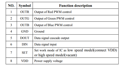
Pin Configuration

Pin Functions
Absolute Max. Ratings

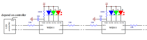
Typical Application Circuits
5V Power Supply – 1 LED – 18.5mA Constant Current
12V Power Supply – 3 LEDs – 18.5mA Constant Current
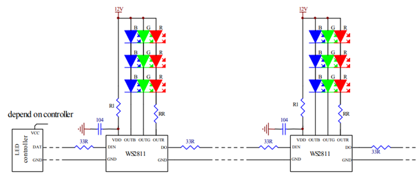
Here the capacitances shown with 104 are bypass capacitors.
33 ohm resistors are suggested on data input/output port for impedance.
R1 is IC internal LDo divider and 2.7kOhm.
Value of the RR can be calculated : RR= (12-3VLEDR)/18.5 kOhm
*(VLEDR is the red LED forward conduction voltage drop)