Analog to Digital Conversion (ADC) – LM335 Temperature Sensor
An analog signal, such as voltage, is converted to a digital form by an analog-to-digital converter (ADC) so that a microcontroller can read and interpret it. ADCs are currently found inside the majority of microcontrollers. Any type of microcontroller can also be connected to an external ADC.
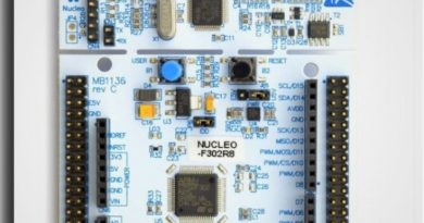
The STM32F302x6/8 devices have only ADC1. The STM32F302xB/C/D/E have ADC1 and ADC2.
In the example we mentioned in this article, we will make an ADC application with the LM335 temperature sensor and see the measurement output on the screen in the RealTerm program we mentioned in our previous article.
You can access the LM335 datasheet and some application examples at the following address;
https://www.st.com/resource/en/datasheet/lm135.pdf
Successive-approximation register, or SAR, is the method utilized in STM ADCs.

Sample and Hold Block
Time and amplitude are both continuous for analog signals. Analog signal amplitude sampling at predetermined intervals is the initial stage in converting an analog signal to a digital signal.
Quantize Block
Digital word values are the output of the quantization block; these are cascaded into a stream of bits for transmission across serial networks. At the receiving end, the signal can be rebuilt after the bits have been retrieved.
HAL and ADC Module
As was mentioned earlier when addressing GPIO pins and timer peripherals, the HAL framework employs a similar C struct to declare ADC peripherals.
ADC Conversion Modes
Using one or more input channels with an ADC can be done in a number typical ways.
These approaches are referred to as conversion modes, and we’ll discuss the most well-liked conversion modes next.
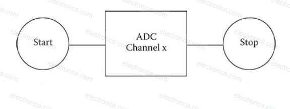
Single Channel and Single Conversion
The most basic mode is this one. In this mode, the analog-to-digital converter (ADC) captures, or more precisely samples, the analog voltage present on a chosen input line or channel and transforms it to a digital number. The number is then taken out of the ADC and applied to any program that needs it.
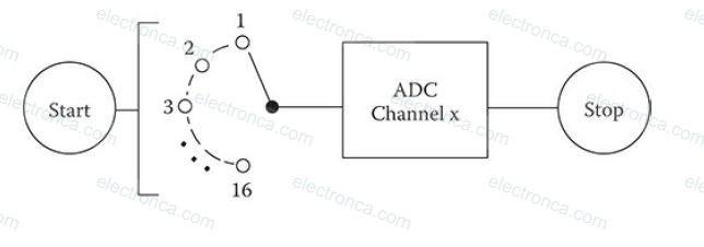
Multi-Channel and Single Conversion
Compared to the previous mode, this one is a little trickier. Several input analog lines are sampled in this mode, and the voltage levels that were sampled are then translated into digital numbers. Each channel is independent in this mode and can be set to have a different sample rate, trigger source, and other customized items. This is one of the mode’s really nice features.
Single Channel – Continuous Conversion
This technique involves continuously sampling a single channel and storing the resulting digital integers in memory. DMA is almost usually used in this mode to reduce the MCU’s excessive burden.
Multi-Channel Scan – Continuous Conversion
This mode constantly samples numerous channels, and the generated digital numbers are then stored in memory. In order to reduce an unacceptable calculation load on the MCU, this mode requires the use of DMA.
Analog Devices – Introduction to the Application – LM335 Temperature Sensor
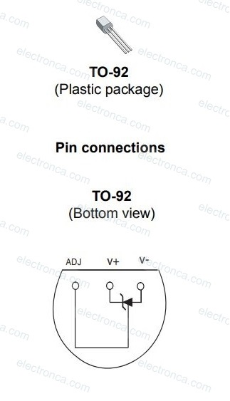
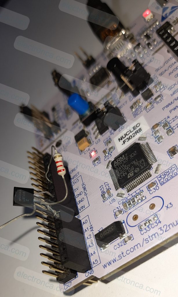
The TO-92 encased model of the LM335 temperature sensor, which will be utilized in this application, is shown in the figure below.
STM CubeMX Settings
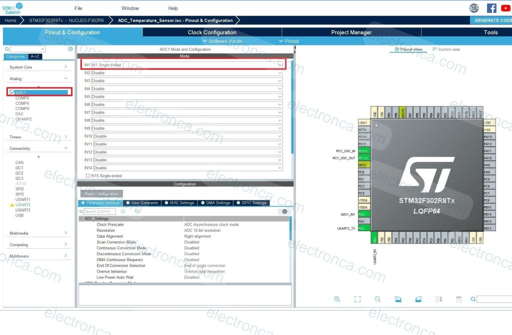
Make the below connection for LM335 temperature sensor on Nucleo Board;
Pin 1 – Idle
Pin 2 – A0
Pin3 – GND
There is also a 2.2k Ohm resistor connected from Pin 2 to 5V.
Example Code – LM335 Temperature Sensor – ADC Conversion
/* USER CODE BEGIN Header */
/**
******************************************************************************
* @file : main.c
* @brief : Main program body
******************************************************************************
* @attention
*
* <h2><center>© Copyright (c) 2023 STMicroelectronics.
* All rights reserved.</center></h2>
*
* This software component is licensed by ST under BSD 3-Clause license,
* the "License"; You may not use this file except in compliance with the
* License. You may obtain a copy of the License at:
* opensource.org/licenses/BSD-3-Clause
*
******************************************************************************
*/
/* USER CODE END Header */
/* Includes ------------------------------------------------------------------*/
#include "main.h"
/* Private includes ----------------------------------------------------------*/
/* USER CODE BEGIN Includes */
/* USER CODE END Includes */
/* Private typedef -----------------------------------------------------------*/
/* USER CODE BEGIN PTD */
/* USER CODE END PTD */
/* Private define ------------------------------------------------------------*/
/* USER CODE BEGIN PD */
/* USER CODE END PD */
/* Private macro -------------------------------------------------------------*/
/* USER CODE BEGIN PM */
/* USER CODE END PM */
/* Private variables ---------------------------------------------------------*/
ADC_HandleTypeDef hadc1;
UART_HandleTypeDef huart2;
/* USER CODE BEGIN PV */
//Private variables
double value = 1.0;
double raw = 0.0;
char msg[20] = "";
/* USER CODE END PV */
/* Private function prototypes -----------------------------------------------*/
void SystemClock_Config(void);
static void MX_GPIO_Init(void);
static void MX_ADC1_Init(void);
static void MX_USART2_UART_Init(void);
/* USER CODE BEGIN PFP */
/* USER CODE END PFP */
/* Private user code ---------------------------------------------------------*/
/* USER CODE BEGIN 0 */
/* USER CODE END 0 */
/**
* @brief The application entry point.
* @retval int
*/
int main(void)
{
/* USER CODE BEGIN 1 */
/* USER CODE END 1 */
/* MCU Configuration--------------------------------------------------------*/
/* Reset of all peripherals, Initializes the Flash interface and the Systick. */
HAL_Init();
/* USER CODE BEGIN Init */
/* USER CODE END Init */
/* Configure the system clock */
SystemClock_Config();
/* USER CODE BEGIN SysInit */
/* USER CODE END SysInit */
/* Initialize all configured peripherals */
MX_GPIO_Init();
MX_ADC1_Init();
MX_USART2_UART_Init();
/* USER CODE BEGIN 2 */
/* USER CODE END 2 */
/* Infinite loop */
/* USER CODE BEGIN WHILE */
while (1)
  {
    /* USER CODE END WHILE */

    /* USER CODE BEGIN 3 */
			HAL_ADC_Start(&hadc1); //starts the ADC1 internal peripheral
			HAL_ADC_PollForConversion(&hadc1, 100); //wait for an end-of-conversation (EOC) to proceed next instruciton
																							//100 is max. in milliseconds to wait EOC signal
			raw = (double) HAL_ADC_GetValue(&hadc1); //transfer the 12-bit value(max. 4095 = 5V) from ADC output register to raw variable
			raw = (raw * 1024)/5000;	//conversation from a raw count to an absolute mV output
			value = ((raw/10)-32)/1.80; //mV to C°
			sprintf(msg, "%f\r\n", value);
			HAL_UART_Transmit(&huart2, (uint8_t*) msg, 20, 100); //UART of MCU to terminal program
			HAL_Delay(1000); // 1 second delay for each sample
  }
  /* USER CODE END 3 */
}
/**
* @brief System Clock Configuration
* @retval None
*/
void SystemClock_Config(void)
{
RCC_OscInitTypeDef RCC_OscInitStruct = {0};
RCC_ClkInitTypeDef RCC_ClkInitStruct = {0};
RCC_PeriphCLKInitTypeDef PeriphClkInit = {0};
/** Initializes the RCC Oscillators according to the specified parameters
* in the RCC_OscInitTypeDef structure.
*/
RCC_OscInitStruct.OscillatorType = RCC_OSCILLATORTYPE_HSI;
RCC_OscInitStruct.HSIState = RCC_HSI_ON;
RCC_OscInitStruct.HSICalibrationValue = RCC_HSICALIBRATION_DEFAULT;
RCC_OscInitStruct.PLL.PLLState = RCC_PLL_ON;
RCC_OscInitStruct.PLL.PLLSource = RCC_PLLSOURCE_HSI;
RCC_OscInitStruct.PLL.PLLMUL = RCC_PLL_MUL16;
if (HAL_RCC_OscConfig(&RCC_OscInitStruct) != HAL_OK)
{
Error_Handler();
}
/** Initializes the CPU, AHB and APB buses clocks
*/
RCC_ClkInitStruct.ClockType = RCC_CLOCKTYPE_HCLK|RCC_CLOCKTYPE_SYSCLK
|RCC_CLOCKTYPE_PCLK1|RCC_CLOCKTYPE_PCLK2;
RCC_ClkInitStruct.SYSCLKSource = RCC_SYSCLKSOURCE_PLLCLK;
RCC_ClkInitStruct.AHBCLKDivider = RCC_SYSCLK_DIV1;
RCC_ClkInitStruct.APB1CLKDivider = RCC_HCLK_DIV2;
RCC_ClkInitStruct.APB2CLKDivider = RCC_HCLK_DIV1;
if (HAL_RCC_ClockConfig(&RCC_ClkInitStruct, FLASH_LATENCY_2) != HAL_OK)
{
Error_Handler();
}
PeriphClkInit.PeriphClockSelection = RCC_PERIPHCLK_ADC1;
PeriphClkInit.Adc1ClockSelection = RCC_ADC1PLLCLK_DIV1;
if (HAL_RCCEx_PeriphCLKConfig(&PeriphClkInit) != HAL_OK)
{
Error_Handler();
}
}
/**
* @brief ADC1 Initialization Function
* @param None
* @retval None
*/
static void MX_ADC1_Init(void)
{
/* USER CODE BEGIN ADC1_Init 0 */
/* USER CODE END ADC1_Init 0 */
ADC_ChannelConfTypeDef sConfig = {0};
/* USER CODE BEGIN ADC1_Init 1 */
/* USER CODE END ADC1_Init 1 */
/** Common config
*/
hadc1.Instance = ADC1;
hadc1.Init.ClockPrescaler = ADC_CLOCK_ASYNC_DIV1;
hadc1.Init.Resolution = ADC_RESOLUTION_12B;
hadc1.Init.ScanConvMode = ADC_SCAN_DISABLE;
hadc1.Init.ContinuousConvMode = DISABLE;
hadc1.Init.DiscontinuousConvMode = DISABLE;
hadc1.Init.ExternalTrigConvEdge = ADC_EXTERNALTRIGCONVEDGE_NONE;
hadc1.Init.ExternalTrigConv = ADC_SOFTWARE_START;
hadc1.Init.DataAlign = ADC_DATAALIGN_RIGHT;
hadc1.Init.NbrOfConversion = 1;
hadc1.Init.DMAContinuousRequests = DISABLE;
hadc1.Init.EOCSelection = ADC_EOC_SINGLE_CONV;
hadc1.Init.LowPowerAutoWait = DISABLE;
hadc1.Init.Overrun = ADC_OVR_DATA_OVERWRITTEN;
if (HAL_ADC_Init(&hadc1) != HAL_OK)
{
Error_Handler();
}
/** Configure Regular Channel
*/
sConfig.Channel = ADC_CHANNEL_1;
sConfig.Rank = ADC_REGULAR_RANK_1;
sConfig.SingleDiff = ADC_SINGLE_ENDED;
sConfig.SamplingTime = ADC_SAMPLETIME_1CYCLE_5;
sConfig.OffsetNumber = ADC_OFFSET_NONE;
sConfig.Offset = 0;
if (HAL_ADC_ConfigChannel(&hadc1, &sConfig) != HAL_OK)
{
Error_Handler();
}
/* USER CODE BEGIN ADC1_Init 2 */
/* USER CODE END ADC1_Init 2 */
}
/**
* @brief USART2 Initialization Function
* @param None
* @retval None
*/
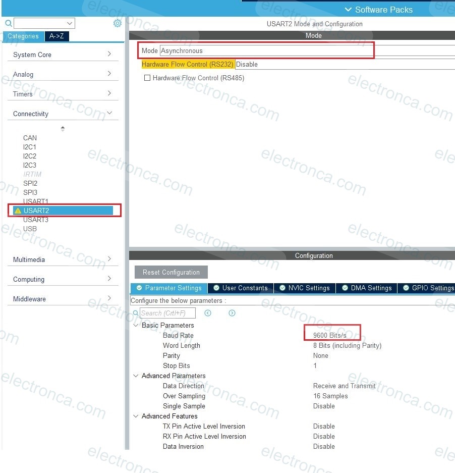
static void MX_USART2_UART_Init(void)
{
/* USER CODE BEGIN USART2_Init 0 */
/* USER CODE END USART2_Init 0 */
/* USER CODE BEGIN USART2_Init 1 */
/* USER CODE END USART2_Init 1 */
huart2.Instance = USART2;
huart2.Init.BaudRate = 9600;
huart2.Init.WordLength = UART_WORDLENGTH_8B;
huart2.Init.StopBits = UART_STOPBITS_1;
huart2.Init.Parity = UART_PARITY_NONE;
huart2.Init.Mode = UART_MODE_TX_RX;
huart2.Init.HwFlowCtl = UART_HWCONTROL_NONE;
huart2.Init.OverSampling = UART_OVERSAMPLING_16;
huart2.Init.OneBitSampling = UART_ONE_BIT_SAMPLE_DISABLE;
huart2.AdvancedInit.AdvFeatureInit = UART_ADVFEATURE_NO_INIT;
if (HAL_UART_Init(&huart2) != HAL_OK)
{
Error_Handler();
}
/* USER CODE BEGIN USART2_Init 2 */
/* USER CODE END USART2_Init 2 */
}
/**
* @brief GPIO Initialization Function
* @param None
* @retval None
*/
static void MX_GPIO_Init(void)
{
/* GPIO Ports Clock Enable */
__HAL_RCC_GPIOF_CLK_ENABLE();
__HAL_RCC_GPIOA_CLK_ENABLE();
}
/* USER CODE BEGIN 4 */
/* USER CODE END 4 */
/**
* @brief This function is executed in case of error occurrence.
* @retval None
*/
void Error_Handler(void)
{
/* USER CODE BEGIN Error_Handler_Debug */
/* User can add his own implementation to report the HAL error return state */
__disable_irq();
while (1)
{
}
/* USER CODE END Error_Handler_Debug */
}
#ifdef USE_FULL_ASSERT
/**
* @brief Reports the name of the source file and the source line number
* where the assert_param error has occurred.
* @param file: pointer to the source file name
* @param line: assert_param error line source number
* @retval None
*/
void assert_failed(uint8_t *file, uint32_t line)
{
/* USER CODE BEGIN 6 */
/* User can add his own implementation to report the file name and line number,
ex: printf("Wrong parameters value: file %s on line %d\r\n", file, line) */
/* USER CODE END 6 */
}
#endif /* USE_FULL_ASSERT */
/************************ (C) COPYRIGHT STMicroelectronics *****END OF FILE****/
We’ve just added the following to the ready-made code that CubeMX has created for Keil IDE.
while (1)
{
/* USER CODE END WHILE */
/* USER CODE BEGIN 3 */
HAL_ADC_Start(&hadc1); //starts the ADC1 internal peripheral
HAL_ADC_PollForConversion(&hadc1, 100); //wait for an end-of-conversation (EOC) to proceed next instruciton
//100 is max. in milliseconds to wait EOC signal
raw = (double) HAL_ADC_GetValue(&hadc1); //transfer the 12-bit value(max. 4095 = 5V) from ADC output register to raw variable
raw = (raw * 1024)/5000; //conversation from a raw count to an absolute mV output
value = ((raw/10)-32)/1.80; //mV to C°
sprintf(msg, "%f\r\n", value);
HAL_UART_Transmit(&huart2, (uint8_t*) msg, 20, 100); //UART of MCU to terminal program
HAL_Delay(1000); // 1 second delay for each sample
}
/* USER CODE END 3 */Output of the Application
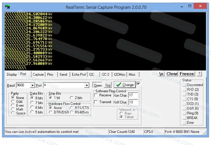
The conversion according to the instantaneous temperature is sent to RealTerm, the Windows Terminal, via USART, and the data is monitored in this way.
If you warm the sensor with your hand (or slightly with the help of a lighter), you can observe that the values (temperature) increase.
also take a look at the Arduino program for the LM335 sensor.