PWM Output on an LED and Servo Motor Control
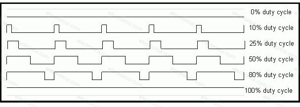
PWM, also known as digital Pulse Width Modulation, is a type of digital on/off signal that pulses up and down at different frequency rates and duty cycles.
The frequency rate, often known as “hertz” or cycles per second, is a measurement of how frequently the pulse repeats.
The duty cycle is the ratio of the pulse’s high and low frequencies.
Digital signals are either on or off, also known as high or low or simply 1 or 0, and are frequently used in conversation. Between on and off, a digital PWM switches.
PWM signals are used for a variety of things.
PWM can control a motor’s speed, an LED’s brightness, or the position of an RC servo.
For instance, a PWM signal with a duty cycle of 50% will work if a 2.5V output signal is required and the PWM signal has a logic high voltage of 5V and a logic low voltage of 0V. With a 50% duty cycle, the PWM delivers 5V for half of the period and 2.5V on average every period.

Vout = A × Duty Cycle
A=Logic ‘high’ voltage amplitude
An advanced or a general purpose (GP) timer is used to produce PWM signals. The method for doing this is described in this topic.
The process of creating the signal is fairly straightforward and involves using an upcounting timer.
The compare capture registers (CCRx) are a set of registers found in every GP timer and are used to store numerical data. The upcounting generates an event based on the timer mode when it reaches that number.

When the count hits 52428, channel 1 is switched to high. The channel stays at a high level until the timer counter reaches the (MAX) number of counts.
The end result of this action is that a 20% duty cycle repeating pulse is emitted from the channel 1 line.
Duty Cycle = (MAX-CCR) / MAX
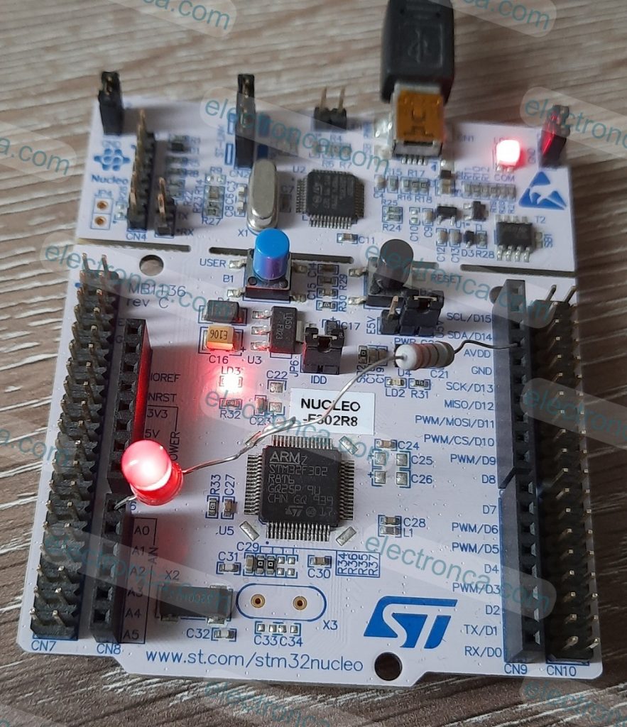
PWM Output on an LED
As we said in our Timers article, if we set the Prescaler value to 655 for our Nucleo Board with a preset clock speed of 64 MHz, we obtain a time of 10.23 microseconds (97.75kHz).
We may attain a very close output period of 20ms by adding setting the Counter Period to 1960.
655/64000000=10.23µs
10.23µS x 1960 =20ms
The CCR1 register was set to 980, which meant that the output changed at a rate of 980 times 10.23µs, or 10.02ms.
All things considered, this is very near to a 50% duty cycle.
Here, the Duty Cycle can be changed by changing the CCR1 value and you can observe the change in LED brightness.

/* USER CODE BEGIN Header */
/**
******************************************************************************
* @file : main.c
* @brief : Main program body
******************************************************************************
* @attention
*
* <h2><center>© Copyright (c) 2023 STMicroelectronics.
* All rights reserved.</center></h2>
*
* This software component is licensed by ST under BSD 3-Clause license,
* the "License"; You may not use this file except in compliance with the
* License. You may obtain a copy of the License at:
* opensource.org/licenses/BSD-3-Clause
*
******************************************************************************
*/
/* USER CODE END Header */
/* Includes ------------------------------------------------------------------*/
#include "main.h"
/* Private includes ----------------------------------------------------------*/
/* USER CODE BEGIN Includes */
/* USER CODE END Includes */
/* Private typedef -----------------------------------------------------------*/
/* USER CODE BEGIN PTD */
/* USER CODE END PTD */
/* Private define ------------------------------------------------------------*/
/* USER CODE BEGIN PD */
/* USER CODE END PD */
/* Private macro -------------------------------------------------------------*/
/* USER CODE BEGIN PM */
/* USER CODE END PM */
/* Private variables ---------------------------------------------------------*/
TIM_HandleTypeDef htim2;
/* USER CODE BEGIN PV */
/* USER CODE END PV */
/* Private function prototypes -----------------------------------------------*/
void SystemClock_Config(void);
static void MX_GPIO_Init(void);
static void MX_TIM2_Init(void);
/* USER CODE BEGIN PFP */
/* USER CODE END PFP */
/* Private user code ---------------------------------------------------------*/
/* USER CODE BEGIN 0 */
/* USER CODE END 0 */
/**
* @brief The application entry point.
* @retval int
*/
int main(void)
{
/* USER CODE BEGIN 1 */
/* USER CODE END 1 */
/* MCU Configuration--------------------------------------------------------*/
/* Reset of all peripherals, Initializes the Flash interface and the Systick. */
HAL_Init();
/* USER CODE BEGIN Init */
/* USER CODE END Init */
/* Configure the system clock */
SystemClock_Config();
/* USER CODE BEGIN SysInit */
/* USER CODE END SysInit */
/* Initialize all configured peripherals */
MX_GPIO_Init();
MX_TIM2_Init();
/* USER CODE BEGIN 2 */
HAL_TIM_PWM_Start(&htim2, TIM_CHANNEL_1);
TIM2->CCR1 = 980; //%50 Duty Cycle for CCR1 register
/* USER CODE END 2 */
/* Infinite loop */
/* USER CODE BEGIN WHILE */
while (1)
{
/* USER CODE END WHILE */
/* USER CODE BEGIN 3 */
}
/* USER CODE END 3 */
}
/**
* @brief System Clock Configuration
* @retval None
*/
void SystemClock_Config(void)
{
RCC_OscInitTypeDef RCC_OscInitStruct = {0};
RCC_ClkInitTypeDef RCC_ClkInitStruct = {0};
/** Initializes the RCC Oscillators according to the specified parameters
* in the RCC_OscInitTypeDef structure.
*/
RCC_OscInitStruct.OscillatorType = RCC_OSCILLATORTYPE_HSI;
RCC_OscInitStruct.HSIState = RCC_HSI_ON;
RCC_OscInitStruct.HSICalibrationValue = RCC_HSICALIBRATION_DEFAULT;
RCC_OscInitStruct.PLL.PLLState = RCC_PLL_ON;
RCC_OscInitStruct.PLL.PLLSource = RCC_PLLSOURCE_HSI;
RCC_OscInitStruct.PLL.PLLMUL = RCC_PLL_MUL16;
if (HAL_RCC_OscConfig(&RCC_OscInitStruct) != HAL_OK)
{
Error_Handler();
}
/** Initializes the CPU, AHB and APB buses clocks
*/
RCC_ClkInitStruct.ClockType = RCC_CLOCKTYPE_HCLK|RCC_CLOCKTYPE_SYSCLK
|RCC_CLOCKTYPE_PCLK1|RCC_CLOCKTYPE_PCLK2;
RCC_ClkInitStruct.SYSCLKSource = RCC_SYSCLKSOURCE_PLLCLK;
RCC_ClkInitStruct.AHBCLKDivider = RCC_SYSCLK_DIV1;
RCC_ClkInitStruct.APB1CLKDivider = RCC_HCLK_DIV2;
RCC_ClkInitStruct.APB2CLKDivider = RCC_HCLK_DIV1;
if (HAL_RCC_ClockConfig(&RCC_ClkInitStruct, FLASH_LATENCY_2) != HAL_OK)
{
Error_Handler();
}
}
/**
* @brief TIM2 Initialization Function
* @param None
* @retval None
*/
static void MX_TIM2_Init(void)
{
/* USER CODE BEGIN TIM2_Init 0 */
/* USER CODE END TIM2_Init 0 */
TIM_ClockConfigTypeDef sClockSourceConfig = {0};
TIM_MasterConfigTypeDef sMasterConfig = {0};
TIM_OC_InitTypeDef sConfigOC = {0};
/* USER CODE BEGIN TIM2_Init 1 */
/* USER CODE END TIM2_Init 1 */
htim2.Instance = TIM2;
htim2.Init.Prescaler = 655;
htim2.Init.CounterMode = TIM_COUNTERMODE_UP;
htim2.Init.Period = 1960;
htim2.Init.ClockDivision = TIM_CLOCKDIVISION_DIV1;
htim2.Init.AutoReloadPreload = TIM_AUTORELOAD_PRELOAD_DISABLE;
if (HAL_TIM_Base_Init(&htim2) != HAL_OK)
{
Error_Handler();
}
sClockSourceConfig.ClockSource = TIM_CLOCKSOURCE_INTERNAL;
if (HAL_TIM_ConfigClockSource(&htim2, &sClockSourceConfig) != HAL_OK)
{
Error_Handler();
}
if (HAL_TIM_PWM_Init(&htim2) != HAL_OK)
{
Error_Handler();
}
sMasterConfig.MasterOutputTrigger = TIM_TRGO_RESET;
sMasterConfig.MasterSlaveMode = TIM_MASTERSLAVEMODE_DISABLE;
if (HAL_TIMEx_MasterConfigSynchronization(&htim2, &sMasterConfig) != HAL_OK)
{
Error_Handler();
}
sConfigOC.OCMode = TIM_OCMODE_PWM1;
sConfigOC.Pulse = 0;
sConfigOC.OCPolarity = TIM_OCPOLARITY_HIGH;
sConfigOC.OCFastMode = TIM_OCFAST_DISABLE;
if (HAL_TIM_PWM_ConfigChannel(&htim2, &sConfigOC, TIM_CHANNEL_1) != HAL_OK)
{
Error_Handler();
}
/* USER CODE BEGIN TIM2_Init 2 */
/* USER CODE END TIM2_Init 2 */
HAL_TIM_MspPostInit(&htim2);
}
/**
* @brief GPIO Initialization Function
* @param None
* @retval None
*/
static void MX_GPIO_Init(void)
{
/* GPIO Ports Clock Enable */
__HAL_RCC_GPIOA_CLK_ENABLE();
}
/* USER CODE BEGIN 4 */
/* USER CODE END 4 */
/**
* @brief This function is executed in case of error occurrence.
* @retval None
*/
void Error_Handler(void)
{
/* USER CODE BEGIN Error_Handler_Debug */
/* User can add his own implementation to report the HAL error return state */
__disable_irq();
while (1)
{
}
/* USER CODE END Error_Handler_Debug */
}
#ifdef USE_FULL_ASSERT
/**
* @brief Reports the name of the source file and the source line number
* where the assert_param error has occurred.
* @param file: pointer to the source file name
* @param line: assert_param error line source number
* @retval None
*/
void assert_failed(uint8_t *file, uint32_t line)
{
/* USER CODE BEGIN 6 */
/* User can add his own implementation to report the file name and line number,
ex: printf("Wrong parameters value: file %s on line %d\r\n", file, line) */
/* USER CODE END 6 */
}
#endif /* USE_FULL_ASSERT */
/************************ (C) COPYRIGHT STMicroelectronics *****END OF FILE****/

Servo Motor Control with PWM
A servo motor is an electric motor with an electronic circuit integrated that transforms particular pulse widths into proportionate rotation.
The restrictions on a servo’s rotation will vary depending on the servo in question, however a neutral position will always be at or near a pulse width of 1.5 milliseconds (ms).

There are 3 cables on the SG90 model servo motor we used in this project. Of these, we will connect the brown one to GND, the red one to 5V, and the orange one to A0 on the CN8 connector.
However, because of lax tolerances, the degree of rotation is frequently 10° to 15°, give or take a few degrees. We are adding to the forever while loop just to add functionality to our ready-made code from CubeMX and to provide continuous return;
/* USER CODE BEGIN Header */
/**
******************************************************************************
* @file : main.c
* @brief : Main program body
******************************************************************************
* @attention
*
* <h2><center>© Copyright (c) 2023 STMicroelectronics.
* All rights reserved.</center></h2>
*
* This software component is licensed by ST under BSD 3-Clause license,
* the "License"; You may not use this file except in compliance with the
* License. You may obtain a copy of the License at:
* opensource.org/licenses/BSD-3-Clause
*
******************************************************************************
*/
/* USER CODE END Header */
/* Includes ------------------------------------------------------------------*/
#include "main.h"
/* Private includes ----------------------------------------------------------*/
/* USER CODE BEGIN Includes */
/* USER CODE END Includes */
/* Private typedef -----------------------------------------------------------*/
/* USER CODE BEGIN PTD */
/* USER CODE END PTD */
/* Private define ------------------------------------------------------------*/
/* USER CODE BEGIN PD */
/* USER CODE END PD */
/* Private macro -------------------------------------------------------------*/
/* USER CODE BEGIN PM */
/* USER CODE END PM */
/* Private variables ---------------------------------------------------------*/
TIM_HandleTypeDef htim2;
/* USER CODE BEGIN PV */
int PW;
/* USER CODE END PV */
/* Private function prototypes -----------------------------------------------*/
void SystemClock_Config(void);
static void MX_GPIO_Init(void);
static void MX_TIM2_Init(void);
/* USER CODE BEGIN PFP */
/* USER CODE END PFP */
/* Private user code ---------------------------------------------------------*/
/* USER CODE BEGIN 0 */
/* USER CODE END 0 */
/**
* @brief The application entry point.
* @retval int
*/
int main(void)
{
/* USER CODE BEGIN 1 */
/* USER CODE END 1 */
/* MCU Configuration--------------------------------------------------------*/
/* Reset of all peripherals, Initializes the Flash interface and the Systick. */
HAL_Init();
/* USER CODE BEGIN Init */
/* USER CODE END Init */
/* Configure the system clock */
SystemClock_Config();
/* USER CODE BEGIN SysInit */
/* USER CODE END SysInit */
/* Initialize all configured peripherals */
MX_GPIO_Init();
MX_TIM2_Init();
/* USER CODE BEGIN 2 */
HAL_TIM_PWM_Start(&htim2, TIM_CHANNEL_1);
/* USER CODE END 2 */
/* Infinite loop */
/* USER CODE BEGIN WHILE */
while (1)
{
/* USER CODE END WHILE */
PW=98;
while(PW<197)
{
TIM2->CCR1 = PW;
HAL_Delay(20);
PW++;
}
while(PW>97)
{
TIM2->CCR1 = PW;
HAL_Delay(20);
PW--;
}
/* USER CODE BEGIN 3 */
}
/* USER CODE END 3 */
}
/**
* @brief System Clock Configuration
* @retval None
*/
void SystemClock_Config(void)
{
RCC_OscInitTypeDef RCC_OscInitStruct = {0};
RCC_ClkInitTypeDef RCC_ClkInitStruct = {0};
/** Initializes the RCC Oscillators according to the specified parameters
* in the RCC_OscInitTypeDef structure.
*/
RCC_OscInitStruct.OscillatorType = RCC_OSCILLATORTYPE_HSI;
RCC_OscInitStruct.HSIState = RCC_HSI_ON;
RCC_OscInitStruct.HSICalibrationValue = RCC_HSICALIBRATION_DEFAULT;
RCC_OscInitStruct.PLL.PLLState = RCC_PLL_ON;
RCC_OscInitStruct.PLL.PLLSource = RCC_PLLSOURCE_HSI;
RCC_OscInitStruct.PLL.PLLMUL = RCC_PLL_MUL16;
if (HAL_RCC_OscConfig(&RCC_OscInitStruct) != HAL_OK)
{
Error_Handler();
}
/** Initializes the CPU, AHB and APB buses clocks
*/
RCC_ClkInitStruct.ClockType = RCC_CLOCKTYPE_HCLK|RCC_CLOCKTYPE_SYSCLK
|RCC_CLOCKTYPE_PCLK1|RCC_CLOCKTYPE_PCLK2;
RCC_ClkInitStruct.SYSCLKSource = RCC_SYSCLKSOURCE_PLLCLK;
RCC_ClkInitStruct.AHBCLKDivider = RCC_SYSCLK_DIV1;
RCC_ClkInitStruct.APB1CLKDivider = RCC_HCLK_DIV2;
RCC_ClkInitStruct.APB2CLKDivider = RCC_HCLK_DIV1;
if (HAL_RCC_ClockConfig(&RCC_ClkInitStruct, FLASH_LATENCY_2) != HAL_OK)
{
Error_Handler();
}
}
/**
* @brief TIM2 Initialization Function
* @param None
* @retval None
*/
static void MX_TIM2_Init(void)
{
/* USER CODE BEGIN TIM2_Init 0 */
/* USER CODE END TIM2_Init 0 */
TIM_ClockConfigTypeDef sClockSourceConfig = {0};
TIM_MasterConfigTypeDef sMasterConfig = {0};
TIM_OC_InitTypeDef sConfigOC = {0};
/* USER CODE BEGIN TIM2_Init 1 */
/* USER CODE END TIM2_Init 1 */
htim2.Instance = TIM2;
htim2.Init.Prescaler = 655;
htim2.Init.CounterMode = TIM_COUNTERMODE_UP;
htim2.Init.Period = 1960;
htim2.Init.ClockDivision = TIM_CLOCKDIVISION_DIV1;
htim2.Init.AutoReloadPreload = TIM_AUTORELOAD_PRELOAD_DISABLE;
if (HAL_TIM_Base_Init(&htim2) != HAL_OK)
{
Error_Handler();
}
sClockSourceConfig.ClockSource = TIM_CLOCKSOURCE_INTERNAL;
if (HAL_TIM_ConfigClockSource(&htim2, &sClockSourceConfig) != HAL_OK)
{
Error_Handler();
}
if (HAL_TIM_PWM_Init(&htim2) != HAL_OK)
{
Error_Handler();
}
sMasterConfig.MasterOutputTrigger = TIM_TRGO_RESET;
sMasterConfig.MasterSlaveMode = TIM_MASTERSLAVEMODE_DISABLE;
if (HAL_TIMEx_MasterConfigSynchronization(&htim2, &sMasterConfig) != HAL_OK)
{
Error_Handler();
}
sConfigOC.OCMode = TIM_OCMODE_PWM1;
sConfigOC.Pulse = 0;
sConfigOC.OCPolarity = TIM_OCPOLARITY_HIGH;
sConfigOC.OCFastMode = TIM_OCFAST_DISABLE;
if (HAL_TIM_PWM_ConfigChannel(&htim2, &sConfigOC, TIM_CHANNEL_1) != HAL_OK)
{
Error_Handler();
}
/* USER CODE BEGIN TIM2_Init 2 */
/* USER CODE END TIM2_Init 2 */
HAL_TIM_MspPostInit(&htim2);
}
/**
* @brief GPIO Initialization Function
* @param None
* @retval None
*/
static void MX_GPIO_Init(void)
{
/* GPIO Ports Clock Enable */
__HAL_RCC_GPIOA_CLK_ENABLE();
}
/* USER CODE BEGIN 4 */
/* USER CODE END 4 */
/**
* @brief This function is executed in case of error occurrence.
* @retval None
*/
void Error_Handler(void)
{
/* USER CODE BEGIN Error_Handler_Debug */
/* User can add his own implementation to report the HAL error return state */
__disable_irq();
while (1)
{
}
/* USER CODE END Error_Handler_Debug */
}
#ifdef USE_FULL_ASSERT
/**
* @brief Reports the name of the source file and the source line number
* where the assert_param error has occurred.
* @param file: pointer to the source file name
* @param line: assert_param error line source number
* @retval None
*/
void assert_failed(uint8_t *file, uint32_t line)
{
/* USER CODE BEGIN 6 */
/* User can add his own implementation to report the file name and line number,
ex: printf("Wrong parameters value: file %s on line %d\r\n", file, line) */
/* USER CODE END 6 */
}
#endif /* USE_FULL_ASSERT */
/************************ (C) COPYRIGHT STMicroelectronics *****END OF FILE****/