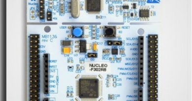
Starting with Nucleo STM32F302R8 and Blinking LED
At the beginning of the article, you can access all the files about the Nucleo F302R8 development board of ST Microelectronics, from this address.

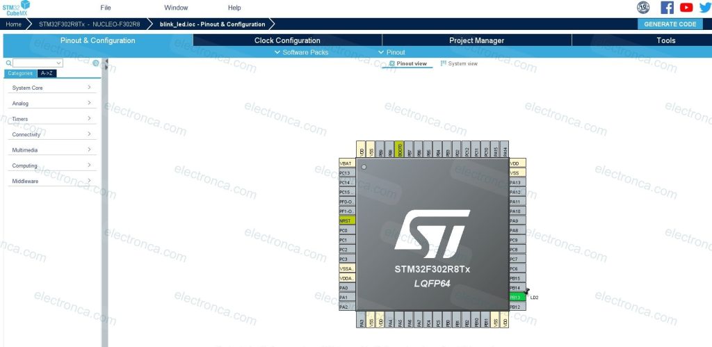
You can access this Pinout diagram from UM1724 User Manual.
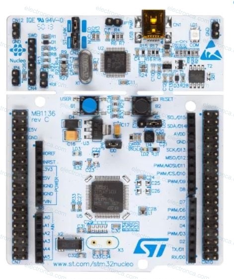
There are LEDs on the Nucleo board. The LD1 is a 3-color LED and provides information about the communication status between St-Link, Computer and MCU.
The second LED, LD2, is a green LED and is connected to the STM32 I/O PB13 pin, which corresponds to the D13 (CN5/CN6) pin of Arduino.
LD3 is a red LED to Show Nucleo-64 board is powered on and 5V power is available.
There are two push buttons also;
B1 User button is connected to I/O PC13 (CN7/23) of the MCU.
B2 Reset button connected to NRST, used to reset MCU.
Towards to the first application..
To create and debug software run on the MCU we’ll need an IDE (integrated development environment).
Here you can download Keil uVision IDE (MDK-ARM).
STM company also shares a useful application called STM32CubeMX with developers. That helps configure MCUs and boards.
STM32CubeMX utility is a GUI-based tool that helps to users create custom configuration files using C language.
For example; this utility can create all the source code required to blink the user LED.
Here you can download it.
Creating an Example Project using CubeMX
We are doing the following application to flash the internal green LED (LD2) on our stm32f302r8 board.
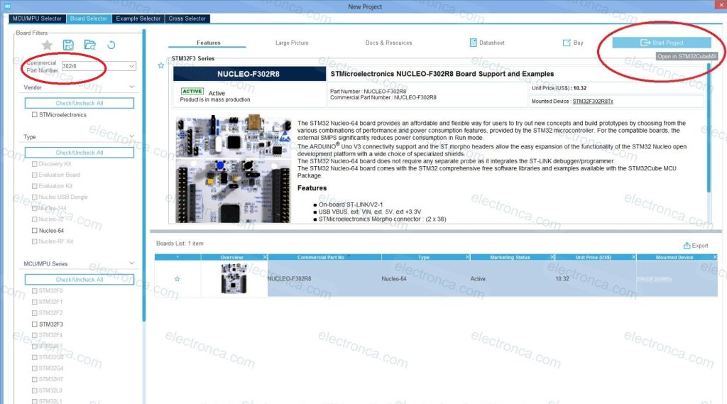
We start by opening a new project in the CubeMX application.
Here we go to the next step by searching and selecting the NUCLEO model that we have.
From the Project Pinout tab, we select and name the pin numbered PB13 (to which LD2 is connected) that we will need.
We fill in the other information sections from the Project Settings section.

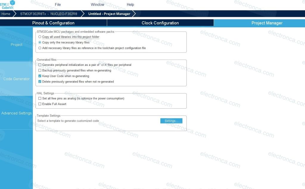
Finally, by clicking Generate Code, we want the application to make the necessary arrangements for us.
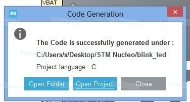
By clicking the Open Project tab on the warning screen, we can open the Keil IDE and start editing the code.
KEIL IDE
The codes created by CubeMX may be daunting at the first stage, but we will only make a few lines of changes at the first stage.
/* USER CODE BEGIN Header */
/**
******************************************************************************
* @file : main.c
* @brief : Main program body
******************************************************************************
* @attention
*
* <h2><center>© Copyright (c) 2023 STMicroelectronics.
* All rights reserved.</center></h2>
*
* This software component is licensed by ST under BSD 3-Clause license,
* the "License"; You may not use this file except in compliance with the
* License. You may obtain a copy of the License at:
* opensource.org/licenses/BSD-3-Clause
*
******************************************************************************
*/
/* USER CODE END Header */
/* Includes ------------------------------------------------------------------*/
#include "main.h"
#include "stm32f3xx_hal.h" //to utilize the HAL framework
/* Private includes ----------------------------------------------------------*/
/* USER CODE BEGIN Includes */
/* USER CODE END Includes */
/* Private typedef -----------------------------------------------------------*/
/* USER CODE BEGIN PTD */
/* USER CODE END PTD */
/* Private define ------------------------------------------------------------*/
/* USER CODE BEGIN PD */
/* USER CODE END PD */
/* Private macro -------------------------------------------------------------*/
/* USER CODE BEGIN PM */
/* USER CODE END PM */
/* Private variables ---------------------------------------------------------*/
/* USER CODE BEGIN PV */
/* USER CODE END PV */
/* Private function prototypes -----------------------------------------------*/
void SystemClock_Config(void);
static void MX_GPIO_Init(void);
/* USER CODE BEGIN PFP */
/* USER CODE END PFP */
/* Private user code ---------------------------------------------------------*/
/* USER CODE BEGIN 0 */
/* USER CODE END 0 */
/**
* @brief The application entry point.
* @retval int
*/
int main(void)
{
/* USER CODE BEGIN 1 */
/* USER CODE END 1 */
/* MCU Configuration--------------------------------------------------------*/
/* Reset of all peripherals, Initializes the Flash interface and the Systick. */
HAL_Init();
/* USER CODE BEGIN Init */
/* USER CODE END Init */
/* Configure the system clock */
SystemClock_Config();
/* USER CODE BEGIN SysInit */
/* USER CODE END SysInit */
/* Initialize all configured peripherals */
MX_GPIO_Init();
/* USER CODE BEGIN 2 */
/* USER CODE END 2 */
/* Infinite loop */
/* USER CODE BEGIN WHILE */
while (1)
{
/* USER CODE END WHILE */
/* USER CODE BEGIN 3 */
HAL_GPIO_TogglePin(LD2_GPIO_Port, LD2_Pin);
HAL_Delay(500);
}
/* USER CODE END 3 */
}
/**
* @brief System Clock Configuration
* @retval None
*/
void SystemClock_Config(void)
{
RCC_OscInitTypeDef RCC_OscInitStruct = {0};
RCC_ClkInitTypeDef RCC_ClkInitStruct = {0};
/** Initializes the RCC Oscillators according to the specified parameters
* in the RCC_OscInitTypeDef structure.
*/
RCC_OscInitStruct.OscillatorType = RCC_OSCILLATORTYPE_HSI;
RCC_OscInitStruct.HSIState = RCC_HSI_ON;
RCC_OscInitStruct.HSICalibrationValue = RCC_HSICALIBRATION_DEFAULT;
RCC_OscInitStruct.PLL.PLLState = RCC_PLL_ON;
RCC_OscInitStruct.PLL.PLLSource = RCC_PLLSOURCE_HSI;
RCC_OscInitStruct.PLL.PLLMUL = RCC_PLL_MUL16;
if (HAL_RCC_OscConfig(&RCC_OscInitStruct) != HAL_OK)
{
Error_Handler();
}
/** Initializes the CPU, AHB and APB buses clocks
*/
RCC_ClkInitStruct.ClockType = RCC_CLOCKTYPE_HCLK|RCC_CLOCKTYPE_SYSCLK
|RCC_CLOCKTYPE_PCLK1|RCC_CLOCKTYPE_PCLK2;
RCC_ClkInitStruct.SYSCLKSource = RCC_SYSCLKSOURCE_PLLCLK;
RCC_ClkInitStruct.AHBCLKDivider = RCC_SYSCLK_DIV1;
RCC_ClkInitStruct.APB1CLKDivider = RCC_HCLK_DIV2;
RCC_ClkInitStruct.APB2CLKDivider = RCC_HCLK_DIV1;
if (HAL_RCC_ClockConfig(&RCC_ClkInitStruct, FLASH_LATENCY_2) != HAL_OK)
{
Error_Handler();
}
}
/**
* @brief GPIO Initialization Function
* @param None
* @retval None
*/
static void MX_GPIO_Init(void)
{
GPIO_InitTypeDef GPIO_InitStruct = {0};
/* GPIO Ports Clock Enable */
__HAL_RCC_GPIOB_CLK_ENABLE();
/*Configure GPIO pin Output Level */
HAL_GPIO_WritePin(LD2_GPIO_Port, LD2_Pin, GPIO_PIN_RESET);
/*Configure GPIO pin : LD2_Pin */
GPIO_InitStruct.Pin = LD2_Pin;
GPIO_InitStruct.Mode = GPIO_MODE_OUTPUT_PP;
GPIO_InitStruct.Pull = GPIO_NOPULL;
GPIO_InitStruct.Speed = GPIO_SPEED_FREQ_LOW;
HAL_GPIO_Init(LD2_GPIO_Port, &GPIO_InitStruct);
}
/* USER CODE BEGIN 4 */
/* USER CODE END 4 */
/**
* @brief This function is executed in case of error occurrence.
* @retval None
*/
void Error_Handler(void)
{
/* USER CODE BEGIN Error_Handler_Debug */
/* User can add his own implementation to report the HAL error return state */
__disable_irq();
while (1)
{
}
/* USER CODE END Error_Handler_Debug */
}
#ifdef USE_FULL_ASSERT
/**
* @brief Reports the name of the source file and the source line number
* where the assert_param error has occurred.
* @param file: pointer to the source file name
* @param line: assert_param error line source number
* @retval None
*/
void assert_failed(uint8_t *file, uint32_t line)
{
/* USER CODE BEGIN 6 */
/* User can add his own implementation to report the file name and line number,
ex: printf("Wrong parameters value: file %s on line %d\r\n", file, line) */
/* USER CODE END 6 */
}
#endif /* USE_FULL_ASSERT */
/************************ (C) COPYRIGHT STMicroelectronics *****END OF FILE****/
Here we have added just the Toggle function to flash the LED using the HAL library and the Delay function for the desired delay time.
/* USER CODE BEGIN 3 */
		HAL_GPIO_TogglePin(LD2_GPIO_Port, LD2_Pin);
		HAL_Delay(500);
/* USER CODE END 3 */
*Note* One of the things that is beneficial to do while developing a project is to write the codes in the specified places. Thus, if you update your project by making a change via CubeMX, the previously written codes will remain in place.
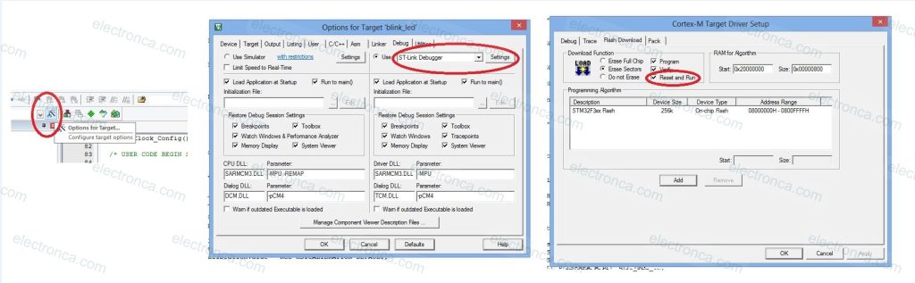
Before downloading the program to the Nucleo Board, we must make the necessary adjustments from the Target Options.
Put a tick in the Reset and Run box to make the program run automatically after it is installed.
After compiling the program and seeing that there is no problem, we make sure that the Nucleo Board is connected to our computer with a USB cable and click the Load tab.
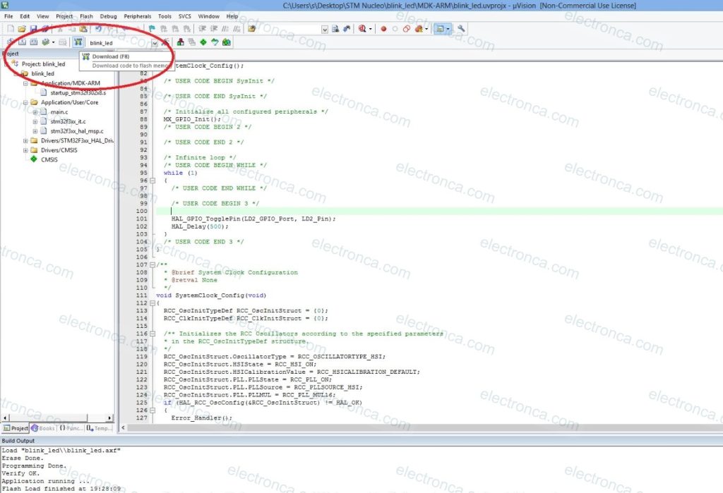
Now you can see the green LD2 pin flashing depending on the set time (500ms).